상품상세정보
▶ Overview
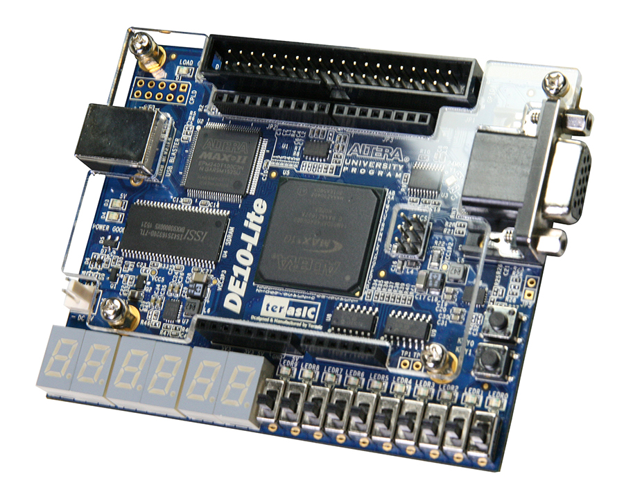
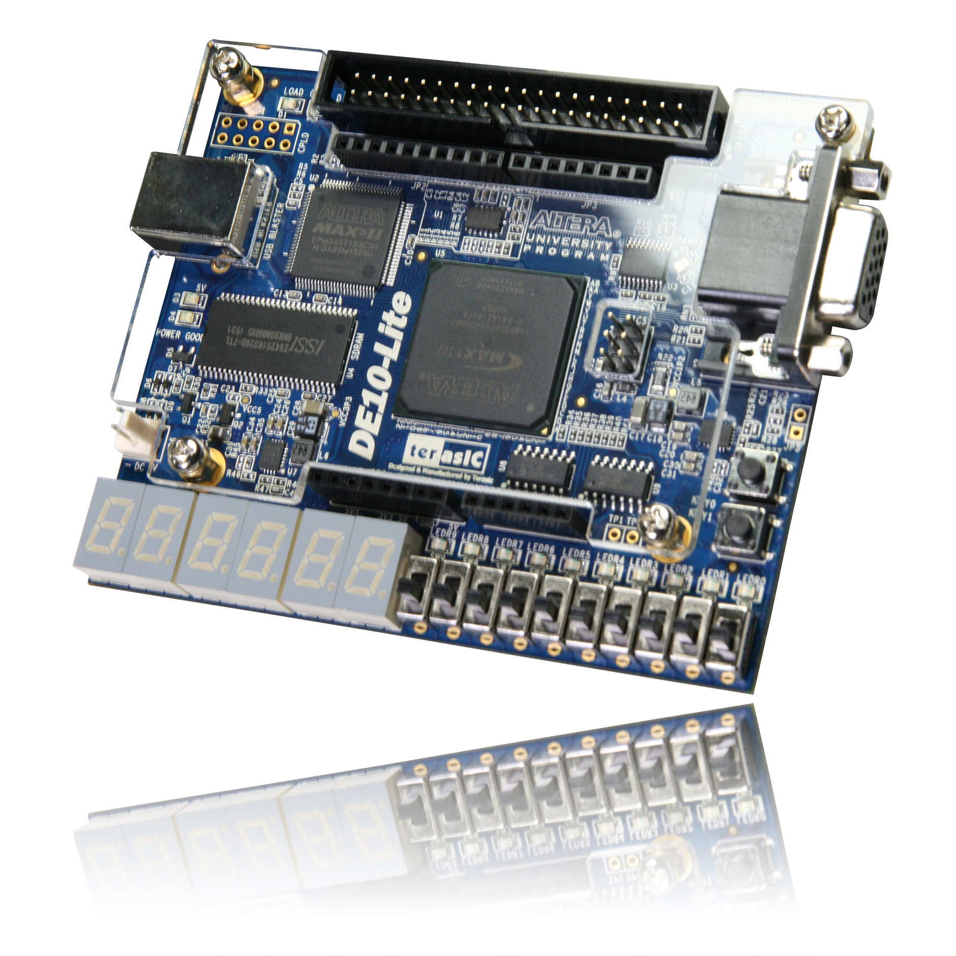
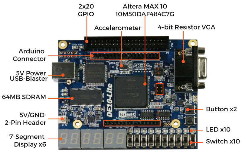
Terasic DE10-Lite is a cost-effective Altera MAX 10 based FPGA board. The board utilizes the maximum capacity MAX 10 FPGA, which has around 50K logic elements(LEs) and on-die analog-to-digital converter (ADC). It features on-board USB-Blaster, SDRAM, accelerometer, VGA output, 2x20 GPIO expansion connector, and an Arduino UNO R3 expansion connector in a compact size. The kit provides the perfect system-level prototyping solution for industrial, automotive, consumer, and many other market applications.
The DE10-Lite kit also contains lots of reference designs and software utilities for users to easily develop their applications based on these design resources.
Component Solution for Altera FPGAs
* SDRAM Memory | * Power Solution, Accelerometer | * Clock Solution |
| |  | |
* Capacitive Component
|
▶ Specifications
This board has many features that allow users to implement a wide range of designed circuits, from simple circuits to various multimedia projects. The following hardware is provided on the board:
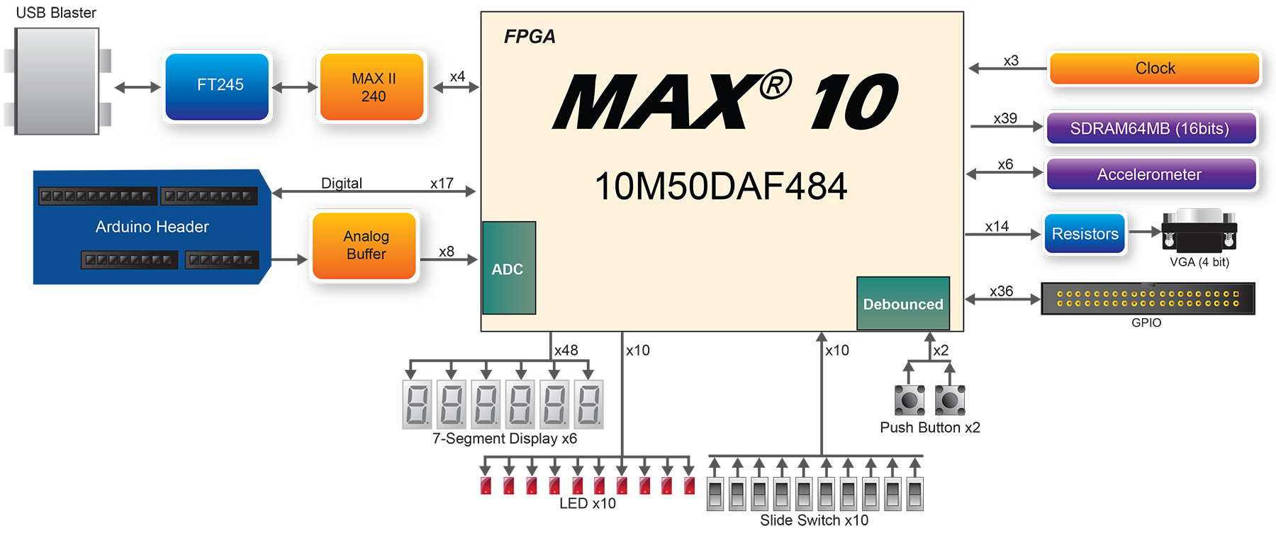
FPGA Device
- MAX 10 10M50DAF484C7G Device
- Integrated dual ADCs, each ADC supports 1 dedicated analog input and 8 dual function pins
- 50K programmable logic elements
- 1,638 Kbit M9K Memory
- 144 18 × 18 Multiplier
- 4 PLLs
Programming and Configuration
- On-Board USB Blaster (Normal type B USB connector)
Memory Device
- 64MB SDRAM, x16 bits data bus
Sensor
- Accelerometer
Expansion Connectors
- One 2x20 GPIO Connector(voltage levels: 3.3V)
- Arduino Uno R3 Connector, including six ADC channels.
Display
- 4-bit Resistor VGA
Switches/Buttons/LEDs/7-Segment Display
- 10 LEDs
- 10 Slide Switches
- 2 Push Buttons
- Six 7-Segments Display
Power
- 5V DC input
Block Diagram of the DE10-Lite Board
Connectivity
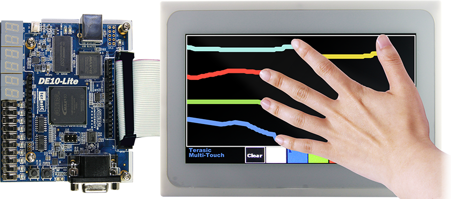
Connect with MTL2
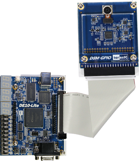
Connect with D8M-GPIO
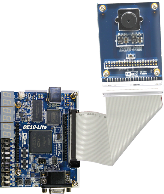
- Connect with D5M
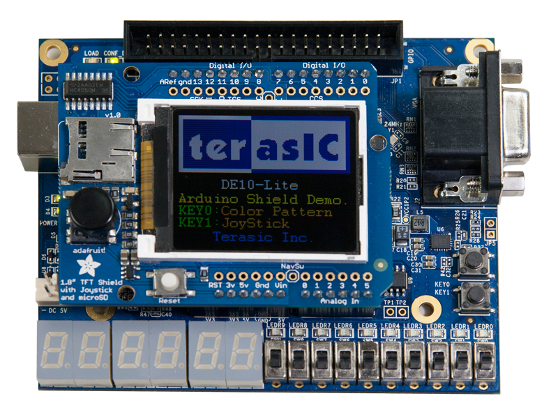
- Connect with Arduino Shield
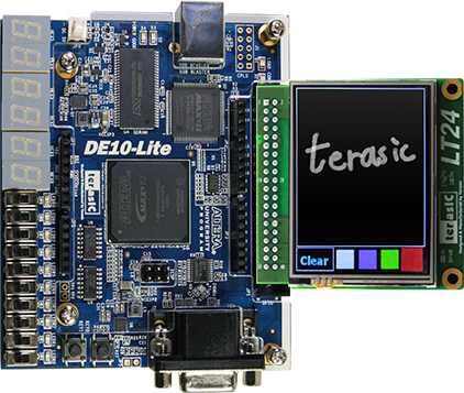
- Connect with LT24
▶ Layout
- Size:97.5*80.0 mm
▶ Resouces
Documents
| Title | Version | Size(KB) | Date Added | Download |
|---|---|---|---|---|
| DE10-Lite User Manual | 1.6 | 5486 | 2018-10-11 |  |
Daughter Card Demonstrations
| Title | Version | Size(KB) | Date Added | Download |
|---|---|---|---|---|
| D8M-GPIO | 2017-05-18 | |||
| LT24 | 2016-09-19 | |||
| MTL2 | 2016-09-19 |
CD-ROM
| Title | Version | Size(KB) | Date Added | Download |
|---|---|---|---|---|
| DE10-Lite CD-ROM | 2.0.3 | 2018-10-11 | ||
| ControlPanel | 1.0.3 | 2018-05-10 | ||
| Quartus Download | 15.1.2 | 2016-06-21 |
3D-Printer-Case
| Title | Version | Size(KB) | Date Added | Download |
|---|---|---|---|---|
| Top cover | 106 | 2016-08-18 |  | |
| Bottom cover | 33 | 2016-08-18 | |
More resources about IP and Dev. Kit are available on Intel User Forums.
Example Designs in System CD
- Factory Default Code
- SDRAM Test in Nios II
- SDRAM Test in Verilog
- VGA Pattern
- Accelerometer Level
- Accelerometer Rock
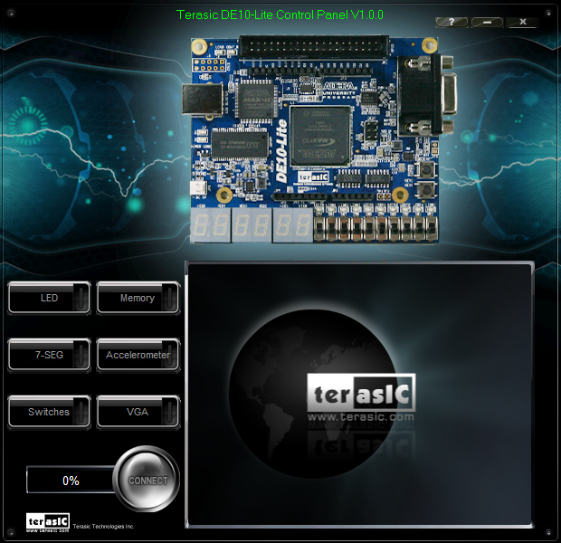
DE10-Lite Control Panel
Allows users to access various components on the DE10-Lite board from a host computer.
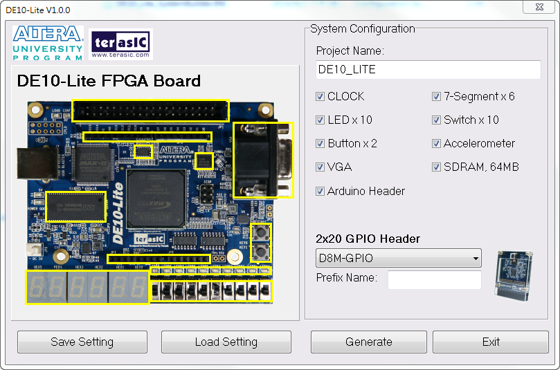
DE10-Lite System Builder
This tool will allow users to create a Quartus II project on their custom design for the DE10-Lite board with the top-level design file, pin assignments, and I/O standard settings automatically generated.
Other course resources you might interested:
School:Cornell UniversitySenior Lecturer - Bruce Land
- Course 1:ECE5760 Advanced Microcontroller Design and system-on-chip [DE2]
- Course 2:ECE5760 Simplified Floating Point for DSP [DE2]
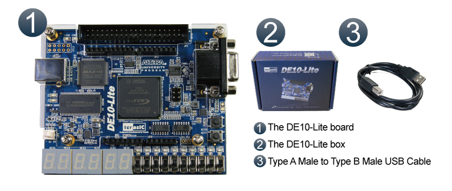
▶ Kit contents
▶ Demo
Demo Download Links:
Themal demo source code: DE10_Lite_FLIR_LAPTON_OnChipMem.zip
Arduino demo source code: DE10-Lite_NIOS_1_8_Display.zip
관련 상품


배송안내
● 이니프로에서 판매하는 모든 제품은 이니프로에서 통관 처리후 우체국 택배로 배송됩니다.
● 국내재고가 있는 경우 결제일로부터 3~4 영업일 안에 국내재고가 없는 경우 결제일로부터 3주 안에 배송됩니다.
● 현재 국내재고가 있는지 확인하시려면 1:1 문의 게시판에 남겨주시거나 sales@inipro.net 으로 메일을 보내주시기 바랍니다.
● 제조사 재고가 부족하여 3주 안에 배송이 어려울 경우 메일로 안내해 드리니 참고하시기 바랍니다.
교환 및 반품안내
● 제품 수령후 7일이내에 이니프로 고객센터에 연락하여 교환 및 반품 처리 요청하면 교환 가능합니다.
● 제품은 박스 상단에 아이디 또는 성함 등을 표기한 후 쇼핑몰 하단의 주소 및 연락처로 택배 발송해 주시기 바랍니다.
● 제품 및 제품포장 박스 등에 손상된 부분이 없는지 고객센터에서 확인한 후 교환 및 반품 처리됩니다.
환불안내
● 제품 수령후 7일이내에 이니프로 고객센터에 연락하여 환불 요청하면 환불 가능합니다.
● 제품은 박스 상단에 아이디 또는 성함 등을 표기한 후 쇼핑몰 하단의 주소 및 연락처로 택배 발송해 주시기 바랍니다.
● 제품 및 제품포장 박스 등에 손상된 부분이 없는지 고객센터에서 확인한 후 환불수수료(5천원+판매가의1%)을 제외한 나머지 금액을 환불 처리해 드립니다.
AS안내
● 제품 보증 기간이 90일인 제품입니다.
● 납품후 90일 이내에는 무상 AS, 90일 이후에는 유상 AS 처리됩니다.
이미지 확대보기DE10-Lite


비밀번호 인증
글 작성시 설정한 비밀번호를 입력해 주세요.
장바구니 담기
상품이 장바구니에 담겼습니다.
바로 확인하시겠습니까?
찜 리스트 담기
상품이 찜 리스트에 담겼습니다.
바로 확인하시겠습니까?
CS CENTER
02-6956-9010문의 및 요청 사항을 1:1 문의 게시판에 남겨주시거나 sales@inipro.net 으로 메일을 보내주시면 최대한 빨리 처리해 드리도록 하겠습니다.
BANK INFO
1005-702-341569우리은행
예금주 : 이니프로주식회사